Control a relay using python
The Relay
Introduction
Relays are switches that can be used to turn on and off high power devices likes fans and bulbs. Imagine if you wanted to turn the lights off in your room by clapping your hands - you will need a relay. If you want to turn on water sprinkler system using code - you need a relay. Basically, any time you need to control devices that operate on high voltages (20V DC to 220V AC), you need a relay.
Objective
- Understand the purpose of a relay.
- Turn a relay on and off using the GPIO pins on the pi.
Prerequisites
Parts
- 1, 2 or 4-channel relay module.
- Breadboard
- Jumper wires
- Dual bench power supply
- 5V power supply (external, not from the pi)
- 3V power supply (external, 2 double AA 1.5V volts will do)
- Raspberry pi
Safety information
Your safety:
A relay module can be used to turn high power devices on and off. Although the experiments here don’t use high power, be aware of the warning:
Live high voltage points are exposed at the bottom of the relay board. If you keep relay board on a metal surface, then the entire surface will be live. That can be extremely hazardous.
In general, be careful if you’re doing anything with mains (i.e 220V). You have been warned.
Your raspberry pi’s safety:
It is possible to “fry your pi” too with this experiment (it rhymes!) and that’s a sad feeling. Make sure you limit the current flowing through the GPIO pins and you should be fine. Opto-isolation is your friend here.
A max of 16mA should be drawn from each of the pins
Power supply
We need a 5V power supply for this experiment. You can use the 5v pin on the GPIO’s but for the safety of your pi a separate voltage source is recommended. We will try out both options (connecting the relay to the pi’s 5v pin should be fine for testing without any load).
Batteries are usually 1.5V or 9V. To get 5V, there are a couple of options:
- Get an external bench power supply. That’s what we will use here.
- Use a 5V USB power adapter. You will need to cut the cables.
- DIY it:
- https://www.instructables.com/5V-Mini-Portable-Power-Supply/
- https://www.youtube.com/watch?v=6PkJvgBFt9Q&t=8s
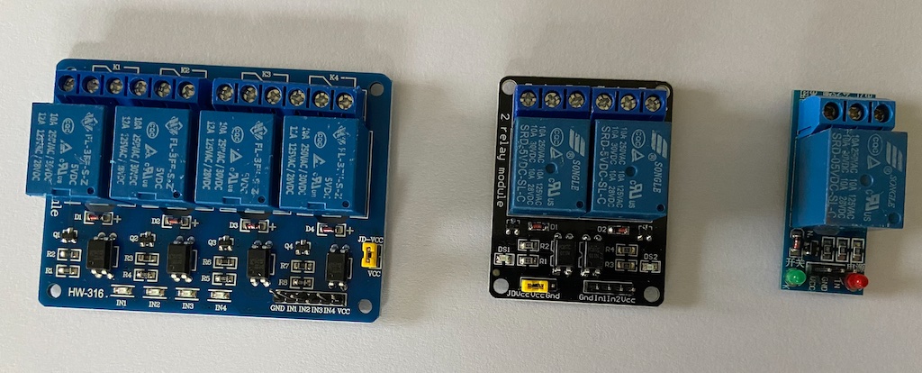
Relay Modules
2-relay module - With opto-isolation
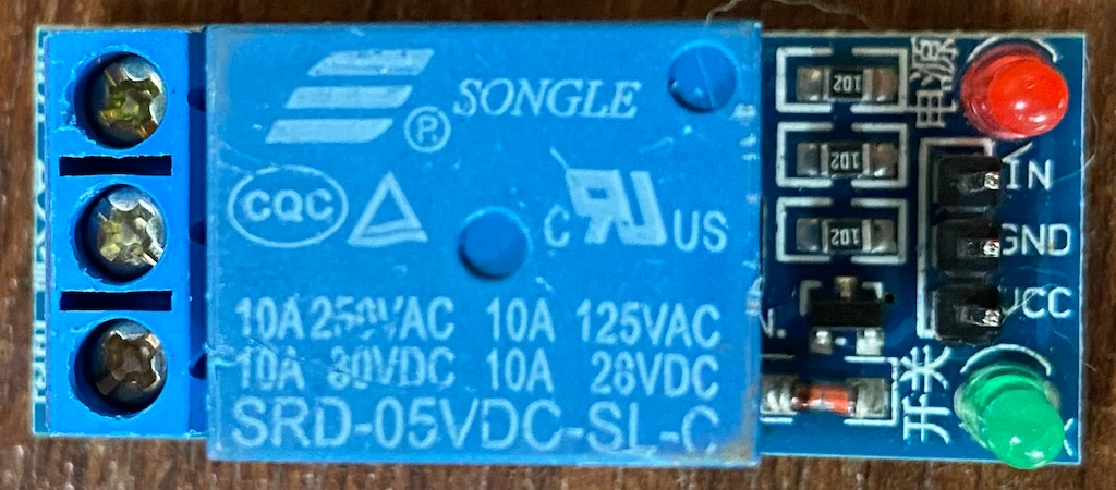
Observe the part of the relay module (HL-52S v1.0) closely.
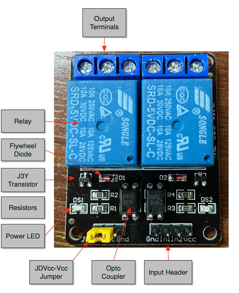
A relay board is a relay with some additional circuitry to needed to connect it to the pi. Board vary a bit, but the one below consists of the following parts:
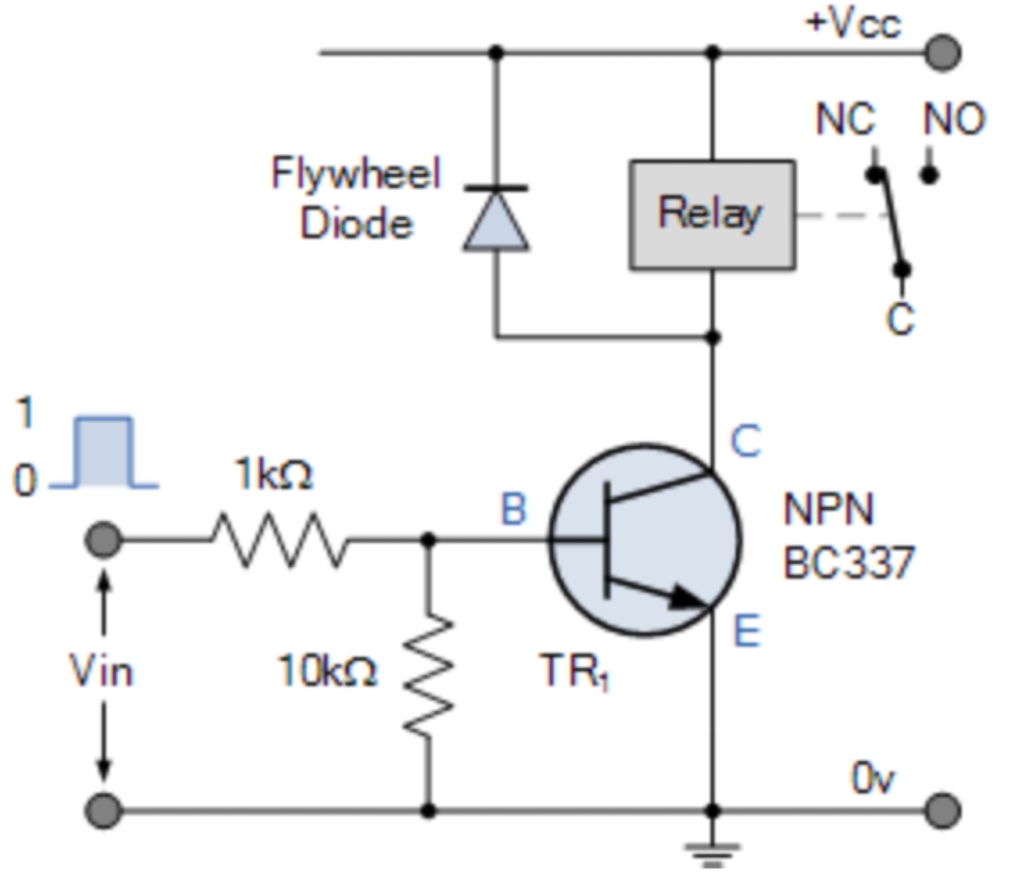
Flywheel diode: When a relay is switched off, a very high volage may be generated momentarily which can damage the pi. A diode connected across the terminals of the electromagnet limits the voltage spike when the relay is de-energized. This is sometimes also called a “snubber” diode.
PC817 Optocoupler: The black 4-pin IC looking device is the optocoupler. It can be used to completely isolate the relay circuit from the circuit connected to the pi thereby protecting the latter. This a secondary protection mechanism for the pi (the flyback diode being the primary one); it is not mandatory, but highly recommended
Relay: The relay itself. That’s the big blue box (or boxes) that contains within it a coil and a switch that turns on when the coil is energized. They come in 5, 12, or 24V indicating the voltage required to drive sufficient current through the coils to turn the switch on and off. When turned on typical loads that the lead terminals can carry is 250V AC at 10A. They can also be used to control upto 30V DC. The ratings are marked on the blue box.
Specs
Operating voltage: 5v
Nominal current: 70 milliamps
Power: 0.36 watts
1K and 100K resistors: They act as current limiting resistors to ensure that the optimal amount of the current is flowing through the optocoupler and the transistor.
J3Y transistor: This is a transistor connected to the phototransistor inside the optocoupler in a darlington pair configuration…which causes the J3Y to sink a lot more current. Enough to energize the relay coil, and pull the switch to ON position.
LED Diodes - DS1: Labelled DS1 these are there to let you know when the relay is active.
JDVcc-Vcc jumper: This is a jumper that connects Vcc to JDVcc. It’s there for convinience in case you want to power the relay (requiring JDVcc) and the pi (requiring Vcc) from the same source, the pi. But for reasons mentioned in 02-relay#High-Trigger-Issue it is better to have this jumper taken off (and put safely in a cupboard). Remember: Connecting Vcc with JDVcc defeats the purpose of even having the opto-isolator in the circuit.
1 relay module - no opto-isolation
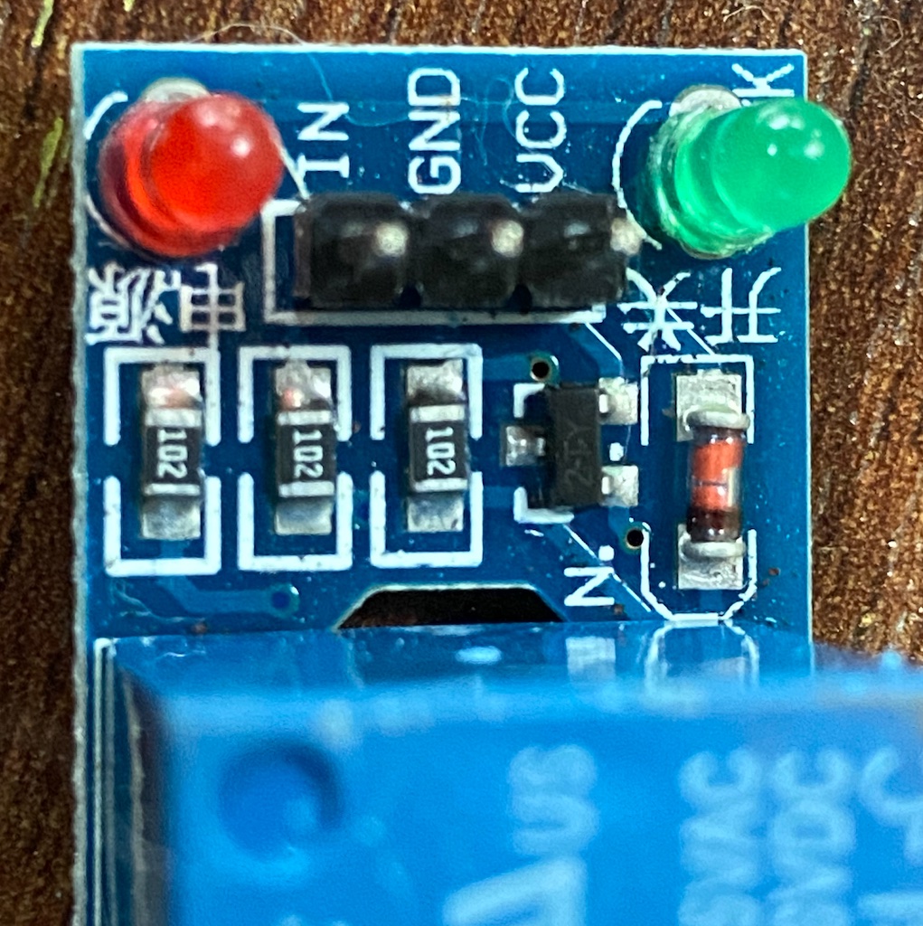
This ciruit does not have the opto-coupler IC device, so both the relay coil and the pi are in the same circuit. However there is still has some protection for the pi - the flyback diode.
When the In1 signal is high, current flows into the transistor, which provides a ground for the relay circuit, and consequently, the relay coil gets energized.
Solid state relays
This solid state relay module has a high trigger option. It requires 160mA and 5V for the relay circuit, and the 3.2V and 2mA for the control circuit.
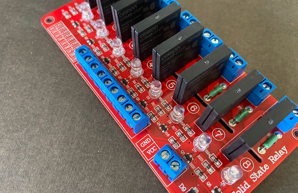
You can see it in “silent” action below.
Experiment 1 - Test the relay
For this experiment we will use the 2-relay module with opto-isolation.
We will test the relay in opto-isolation mode - i.e. the control circuit, and the load circuit are completely isolated. Keep the pi aside for this experiment.
- Remove the JDVcc-Vcc jumper.
- Connect 5V DC to JDVcc terminal.
- Connect the GND pin to the negative terminal of the 5V supply.
- Connect 3.3V DC to Vcc
- Connect a jumper wire to the In1 pin.
- Connect the other end of the jumper wire to -ve end of the 3.3V DC.
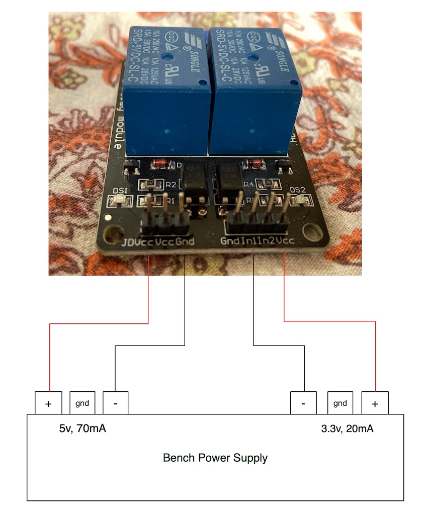
As soon as you connect In1 to ground (or negative terminal), you should hear a clicking sound indicating that the relay switch has turned ON. Additionally, the LED for the first relay should come on as well.
Then repeat the test for In2 terminal too.
References:
Experiment 2 - Connect relay to pi
It’s almost the same as the above except, except the control pins of the relay are now powered by the pi. The relay load pins are as below.
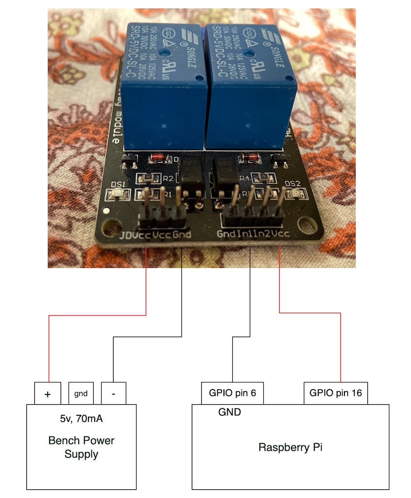
Now boot up your pi and run the following program:
import RPi.GPIO as GPIO
import time

in1 = 16

GPIO.setmode(GPIO.BOARD)
GPIO.setup(in1, GPIO.OUT)

try:

while True:
for x in range(5):
GPIO.output(in1, True)
time.sleep(5)
GPIO.output(in1, False)
time.sleep(5)

except KeyboardInterrupt:
GPIO.cleanup()
If all goes well, you should see the relay switch turn on and off periodically.
Troubleshooting
Understand the relay board
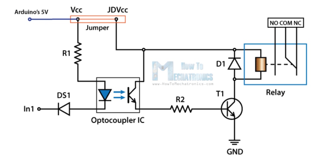
The main problem is a lack of understanding of the board schematic - as there are a few variations out there. Try to get the correct schematic and understand the circuit. The one in this lesson uses the schematic below (can be in two different configuration based on the jumper switch)
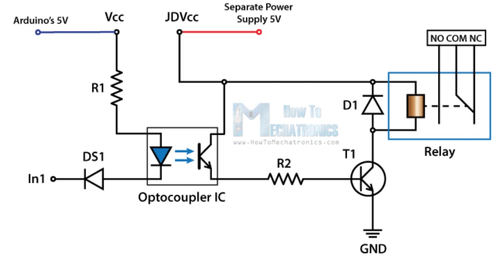
With opto-isolation (recommended)
Without opto-isolation (may work if you’re driving one relay)
Here is a completely different board (not used in this lesson, and not recommended too) that does not even have an opto-isolater. Your pi is protected by the flywheel (aka flyback) diode only.
Use the correct type of relay
 Don’t use this.
There are many types of relay boards you can buy and some are good, some not so. It’s best to avoid the relay board shown above for the following reasons:
- It does not have an opto isolation IC, which means the relay coil and the GPIO pins are part of the same circuit…and the latter are fragile little babies. Yes, there is the flyback diode in the circuit, but an opto-isolation is a second level protection should the diode fail.
- You could connect the Vcc pin to 5V pin of GPIO, and when In1 is LOW, the relay will trigger. But, there are two problems with this:
- The pi will boot up with GPIO pin set to LOW. This means your relay will turn ON as soon as the pi is turned on. You have to wait for your program to start running in order to set it to HIGH to turn it off. Often times, this is not what we want.
- At 5V Vcc, this will draw about 20mA. This may not be dangerous, but it does seem above the nominal rating of what the GPIO pin can handle - which is about 10-15mA.
Instead, use the relay with an opto isolation IC and provide relay with it’s own power as shown in 02-relay#Experiment-2—Connect-relay-to-pi. This solves the GPIO safety issue, and the HIGH/LOW trigger issue.
High Trigger Issue
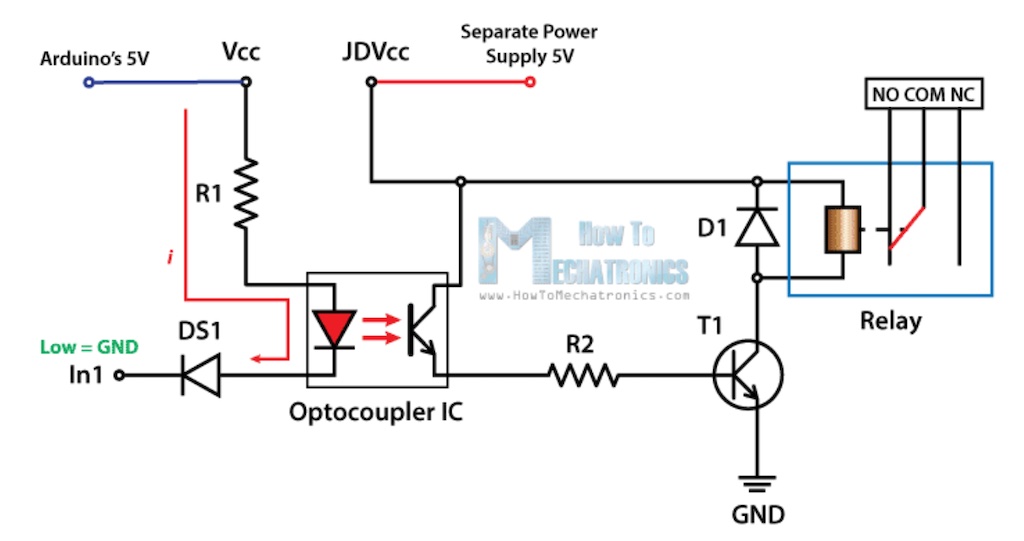
Many places on the Internet will have you connect Vcc to the Raspberry Pi’s Vcc and In1 to the GPIO pin. That will not work very well.
Look at the left side of the above circuit. When the In 1 = LOW, it has 0 volts. That means there is a 5 volts of potential difference across the resistor and diode in the optocoupler - enough to drive enough current through the wires, which triggers the relay circuit. This will cause the trigger as soon as the pi power is available, and not wait till you run your program. Probably not what you want.
Now, the next problem.
Consider what happens when the the In 1 = HIGH, giving it a potential of 3.3 volts. Now the voltage difference across the resistor and led in the optocupler is 5 - 3.3 = 1.7 volts. That might not be enough to stop the current flow…and so some current will keep flowing. This means the relay will NOT turn off (or it might be erratic).
The simple solution is to connect the GPIO pin to Vcc. This will provide about 3V and 10 mA which is sufficient to turn on the transistor inside the opto-coupler IC, which will turn on the relay.
Ensure that In1 is always set to GND.
There is one disadvantage to this approach. You can only control one relay, since there is only Vcc connector on the relay board. If you want to connect another GPIO pin to a second relay, and control them independently you’re out of luck with this approach.
To solve this, there are two more approaches to consider:
- Modify the relay board
- Solution 1: https://alselectro.wordpress.com/tag/relay-boards-with-rpi/
- Solution 2: Get a high level trigger. https://www.sunfounder.com/products/1channel-dc5v-relay-module
Physics
Oersted was the first to detect the connection between electricity and magnetism as he noticed a compass move when near a current carrying wire. The compass is only affected by magnetic field…so it must be that the flowing electrons in wire are causing that magnetic field. This concept bloomed into the electromagnet - a coil of wire which became magnetic when current passed through it, and lost it’s magnetic powers when the current was switched off.
That is what is at the heart of the relay.
Inventors
Four years after Oersted made his stunning discovery, William Sturgeon made the first electromagnet in 1824.
Questions
- Why is there a voltage spike when a coil is de-energized?
- How do solida state relays work?
- What is a phototriac?
Next Steps
In this experiment we turned a relay on and off using the raspberry pi. But we did not actually connect any load to the switch, like a bulb or solenoid, to the relay.
For that, see 03-solenoid.
Glossary and etc
Terms
| Term | Explanation | |
|---|---|---|
| MCU | Microcontroller Unit (i.e, the pi) | |
| Flyback Diode | Dissipates excess current in the coil | |
| Optocoupler | Isolates two circuits |
Links
- https://www.electronicshub.org/control-a-relay-using-raspberry-pi/
- http://baskauf.blogspot.com/2018/02/turning-stuff-on-and-off-using.html
- https://www.tomshardware.com/reviews/raspberry-pi-gpio-pinout,6122.html
- https://www.raspberry-solutions.com/connect-relay-to-raspberry-pi/
- https://www.electronicshub.org/control-a-relay-using-raspberry-pi/
** With opto-isolation**
- https://lastminuteengineers.com/two-channel-relay-module-arduino-tutorial/
- https://sharvielectronics.com/wp-content/uploads/2020/02/2-Channel-12V-Relay-Board-Module-with-Optocoupler.pdf
** With a fix to the high trigger problem **
https://myhydropi.com/connecting-a-relay-board-to-a-raspberry-pi
Using the ULN2803APG chip
Using a 2N222 transistor
tags
#relay, #opto-coupler, #electromagnetism